
There hasn’t been much activity on this blog as of late, as I unfortunately didn’t get out diving over the winter. (Although I did get in some free-diving in on the Sunshine coast!). I have, however, gotten back into the swing of things recently. I haven’t been taking my camera out diving, as I’ve been doing some shakeout dives and working with Josh to help him get ready for finishing Fundies. So dive photos will have to wait. I have, however, been wanting to make some posts about dive equipment. To kick things off, here is some information on my GreenForce HID upgrade.
(Quick note, since this is a “work in progress”, I’m updating and editing this post as I work on the upgrade. There’s a high-level change-log at the bottom of the post)

GreenForce HID50 Head (With Benchmade 7-Hook and Light Monkey Goodman handle)
The Whys of DIY
Anyone who knows me knows that I’m a tinkerer and love DIY projects. Anyone who’s dove with me knows that I have a love/hate relationship with my Greenforce 10w HID light (old HID50). Naturally, the two have collided, and I’m working on replacing the old HID bulb and ballast with an LED with the objective of increasing reliability, light intensity, and hopefully making the dive light better for underwater signalling. Here is how I’m doing this, on a budget.
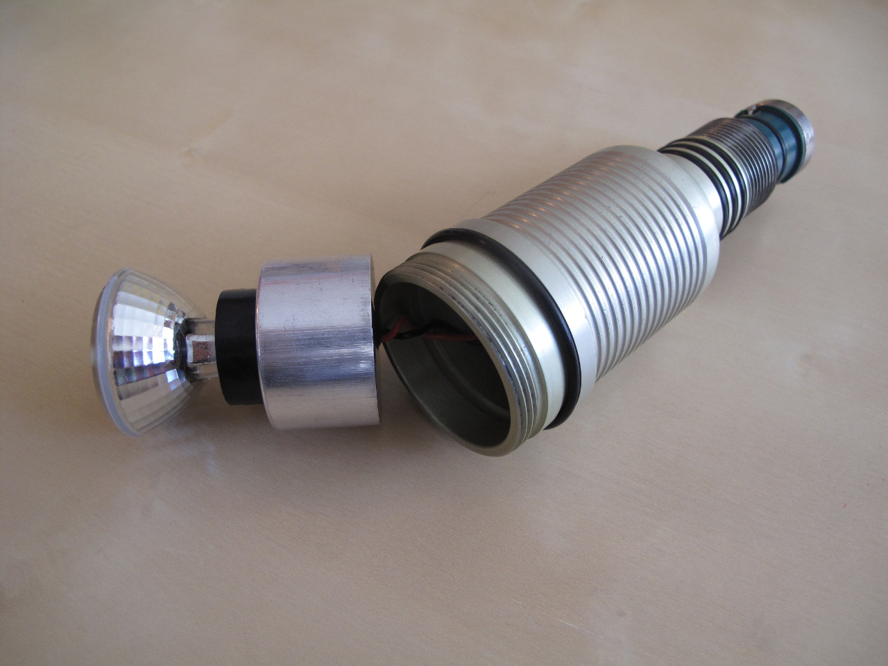
HID50 Light head opened with the HID bulb and ballast visible
To preface this, I think the modular nature of GreenForce lights is a good idea for the underwater video lighting that GreenForce excels at (from my view-from-the-outside). The HID50 light I have is generally well built, and has withstood a lot of abuse over the past 5 or so years I’ve had this light. I’m rough with equipment and somewhat clumsy. The machined aluminum parts are beautiful, and the light-cord is tough but flexible. However, I have for a long time been wrestling with electrical gremlins where the HID light failed to strike, often in the water. Originally I thought this was the ballast, however eventually tracked it down to one of the electrical connections in the umbilical having broken it’s solder joints, probably due to the mechanical stress caused by screwing and un-screwing the connection (which is how the light is turned on and off). Although the soldering joint was broken, there was sometimes enough metal-to-metal contact to make a connection good enough for the HID to strike. The light would typically strike when I turned it on on land, however if I waited to turn it on after a long surface swim in cold water, the light would not strike. I suspect this was due to the contraction in the broken joint introducing enough resistance to keep it from striking. I should note the light has never failed on me during a dive while on. I haven’t heard of anyone else having this problem, so I may have just had bad luck.

GreenForce Umbilical Connection. Note the small joint hidden between the metal ring and the threads.
After re-soldering the joint and applying some epoxy to the ring to keep it in place, hopefully this issue will be fixed. Just note, that if you’re doing this repair yourself, you will require a good, temperature controlled soldering station with sufficient power to heat up the metal ring to make a proper joint. The metal ring has a large heat capacity, and if the soldering iron isn’t up to the job it will lead to a cold-joint liable to breaking again. Also important is to use epoxy to re-affix the ring to the plastic to ensure that the soldering joint is protected from too much mechanical stress.
My second gripe isn’t specific to GreenForce, but more towards the technology from 5 years ago when I got this light. The 10 Watt HID is weak, with a somewhat wide beam, making it insufficient for signalling, even in low-viz daylight situations. Combined with the inherent ageing effects of the HID bulb, it pales in comparison to the intensity of any modern dive lights. This isn’t GreenForce specific, as the Welch-Allyn Solarc HID bulb used by GreenForce was also used in many other big-name manufacturer’s 10 Watt HIDs of that time-frame, so any lights using the same bulb will this issue. Unfortunately, these bulbs are no-longer available so I can’t simply swap in a new 6 degree bulb and hope for the best. GreenForce does have a LED upgrade for the HID50 which looks interesting, however given the cost I’d rather save the money for a 21 Watt HID down the road.
Plus DIY is always more fun. What other reason do you need?
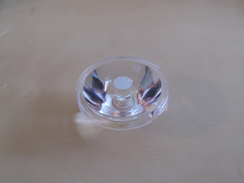
Choosing LEDs and Collimators

TheCree XM-L2 U2 LED — A powerful light in a small package
Looking around, I found a nice bright LED, the XM-L2 U2 by Cree. Depending on the grade and specific part number, this LED will output about ~1000 lumens at 3 amps draw with a forward voltage of 3.35V, resulting in 10 watts consumed by the LED alone. I dug around last summer and found some collimaters from Led-Tech.de (Specifically the LT-1211 and LT-1818) as well as a Carclo 10755 from Digikey.ca. I toyed around with making my own LED driver, but having too many other projects and so little time I recently opted to pick up an inexpensive 3A driver along with pre-mounted XM-L T6 LED from lightmalls.com. (I’m planning on mounting the XM-L2 LED eventually, as it should have a very slight edge on the luminosity output of the XM-L T6). Each optic is fairly inexpensive, so I could easily order a few different models to play around with.
An interesting note, is that according to the specs the Solarc HID+Ballast system draws about 13.8 Watts in system. Using a realistic estimate of 70-80% LED Driver efficiency, the LED system draws about 12.5-14.4 Watts. (I suspect that the “90-95% efficiency” for the LED Driver doesn’t hold true for the case of driving it from ~12 volts at maximum current). Unfortunately my multi-meter can’t measure higher than 200mA current so I can’t test the true power draw/efficiency. The short of this is that the current draw from the canister battery will be nearly the same with the LED, so no worries about reduced burn times or too much discharge current.
Update 31-Dec-13: I picked up a 0.1 Ohm resistor, and used it to measure the current draw of the LED. From the battery, it draws about 1.37 Amps, netting about 66% efficiency assuming 3 Amps into the LED at 3.6 Volts and straight up 12V from the battery. Not that great — Definitely makes a case for making a more optimized driver. Granted, I didn’t re-measure the actual battery voltage under load, but it should be near enough to 12 Volts.
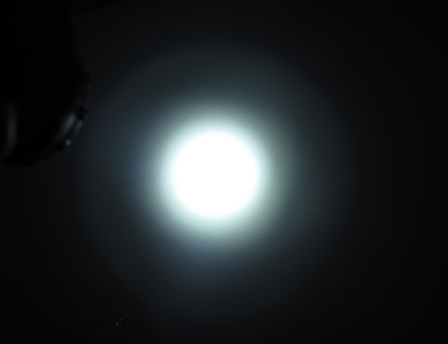
Quickly hooking everything up, below is a comparison of the current HID bulb, and each of the two lenses with the XM-L T6 LED. Note that all photos were taken with my camera in manual-mode with the same settings. The photos are pointing at the white ceiling with the white-balancing set to “daylight” on my PowerShot G10. (The last two were taken a week later, with the same conditions and settings)
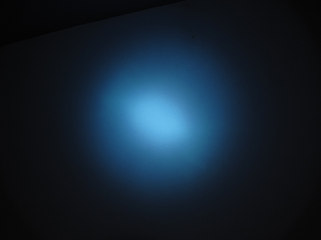
Original Welch-Allyn Solarc 10W HID (~5 years old)
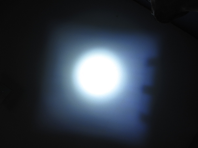
XM-L T6 with Gaggione Mobdar Collimator (LT-1211)
XM-L T6 with Gaggione LLS05 Collimator (LT-1818)
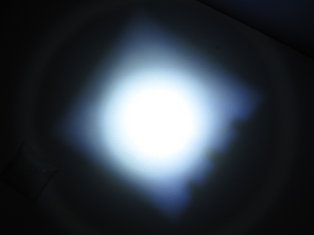
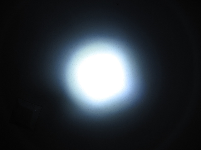
XM-L T6 with Carclo 10755 Collimator
Although not overly scientific, I tried to keep everything in the pictures as constant as possible, and the batteries fully charged. Note that the LEDs all saturated the camera’s sensor in the center of the beam.

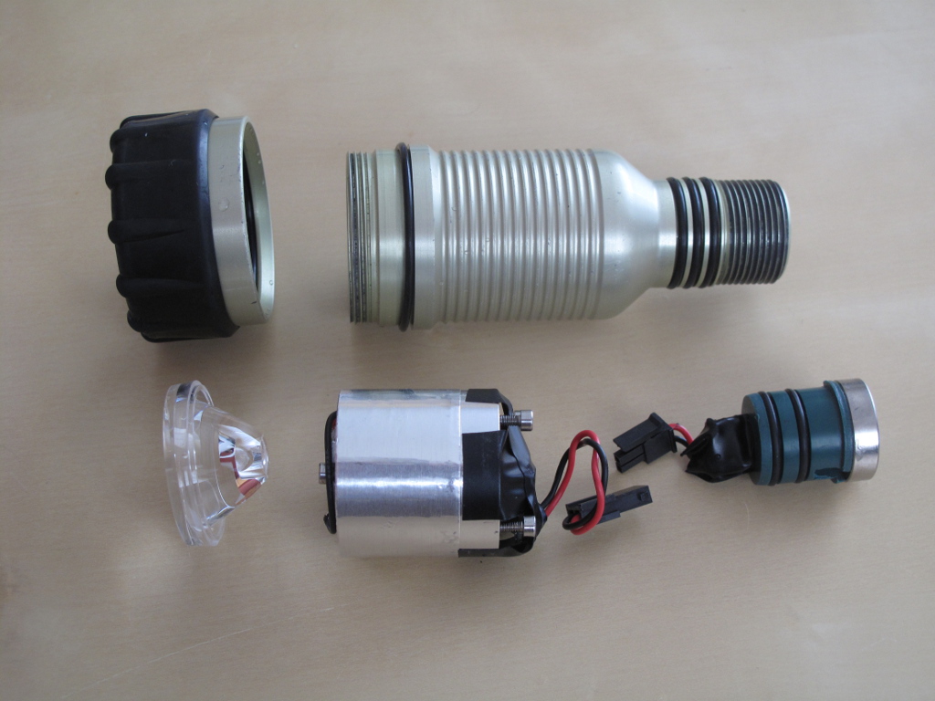
From top left to bottom right: Greenforce power “plug”, HID Ballast, LED with Driver (and aluminum block for a test heatsink), Welch Allyn Solarc 10W HID bulb, LT-1211, LT-1818 and Carclo 10755
Looking at the photos above, it is obvious how much brighter the LED will be compared to the old HID bulb. The beam-widths aren’t quite as tight as I would like, but hopefully with the added power they will be better for signalling than the current bulb. Note that I just had the collimators resting on the LED board, so they may not have been lined up perfectly. Underwater, due to the differing refractive index, the beam should be a bit tighter than above. Interesting to note, the LT-1211 and Carclo optics both throw off a bit of a square spill.
An interesting note when considering beam-widths, manufacturers (both lens/collimator manufacturers as well as dive light manufacturers) don’t always specify what their beamwidth is — Typically it should be the width to the half-power point, but this can vary depending on how the manufacturer wants to market their light. Some manufacturers take the center of the beam to half power, and others take half-power to half-power (twice the center to half-power). This can lead to quite a bit of variance in specifications.
Facing the Heat
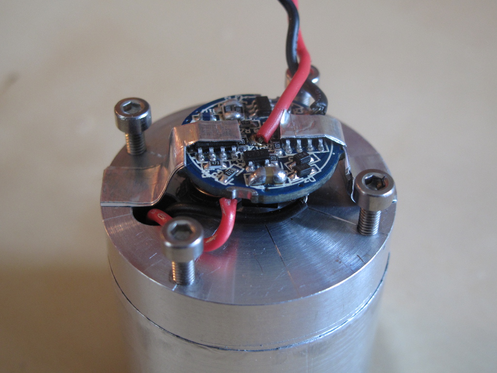
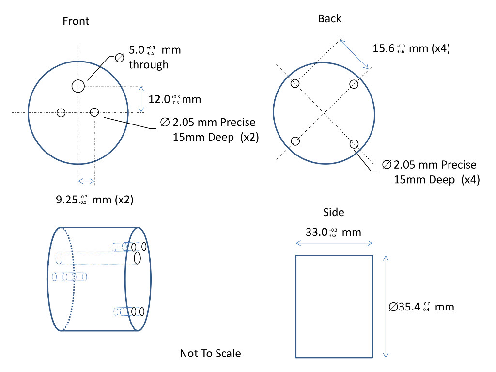
The final components, including the LED/Heatsink/Driver assembly
The LED sheds a lot of heat when powered at full current. The PCB that the LED is mounted on actually has an aluminum substrate, allowing a thermally efficient connection to a heatsink. I whipped up a quick design to both mount the LED within the lighthead as well as to act as a heatsink to trasnfer heat from the LED to the aluminum lighthead case, which will then shed the heat to ambient.
My Dad helped me out by spinning the part for me out of 6061 Aluminum on his lathe (It sucks not having my own machine tools out here!). There are four screws in the back of the heatsink which I can use to set the depth at which it sits inside the light head, so I can swap out collimators of different sizes if I so desire. I was a bit conservative when specifying the diameter of the heatsink, which resulted in a small gap. Wrapping the heatsink with aluminum foil tape solved this problem nicely, making it fit snugly within the light head.
LED Driver on Heatsink, with Aluminum “Fingers”
The LED board is screwed tightly into place, with a thermal compound to ensure good heat transfer. On the other side, the LED Driver board has no convenient mounting points. I opted to mount it with the inductor against the heatsink, as there were no other convenient flat spots that wouldn’t cause any short circuiting. I suspect that the driver wasn’t designed for continuous use, as it does heat up fairly quickly with no obvious ways to reduce the heat. To try and alleviate this, I used several layers of aluminum tape to make “fingers” to conduct a little bit of heat away from the top components. It works surprisingly well.
The best solution to this will be to build a proper LED driver, which can be mounted directly onto the heatsink itself. There are several LED driver ICs with varying levels of integration and efficiency so I’ll have to do some research to find the optimal choice . The added benefit to making a custom driver is that an under-voltage lockout circuit can be added, to ensure that the canister’s battery isn’t discharged to the point of being damaged. (There are arguments against this, but since I don’t plan to use this particular light for extreme dives lasting longer than the ~4.5+ hours of estimated burn time, I would rather have the canister batteries last rather than be damaged pulling every last second of burn time out of the system).
For the time being the “budget” driver is sufficient.
Battery Pack Woes
During my burn tests I noticed that at around the 2:50 hour mark the LED would dim for under a second, then go back to full intensity for a few minutes before repeating. I was perplexed by this and initially thought that the driver was over-heating and entering a heat-fault mode. Theoretically, I should be getting at the very least a 3:45 hour burn time, using a conservative 70% efficiency estimate for the driver, with the batteries rated at 4500 mAh when they were new.

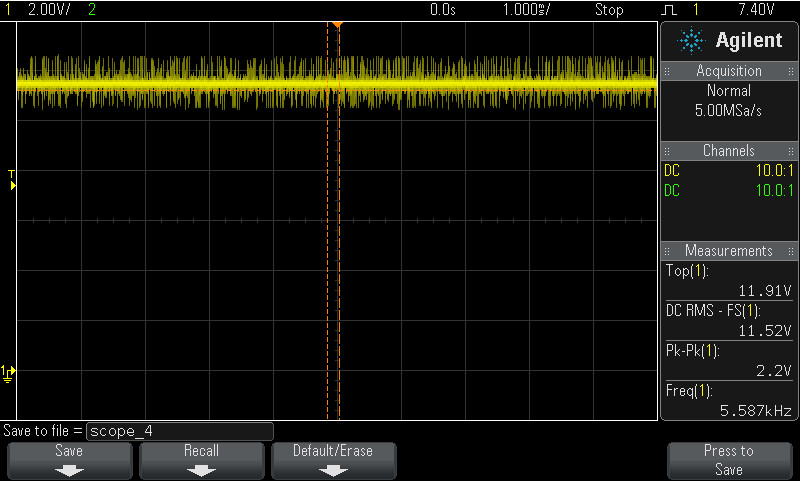
Battery Voltage after 2:50 Hours
For fun, I decided to hook up my oscilloscope to the driver to see what the switching frequency was and try to find anything “funny”. It’s a good thing I did. The screen grab to the right is the battery voltage leading into the driver. (It was the same whether through the umbilical or straight to the canister). When the battery is fresh, this is a straight (albeit noisy from the driver) line around 12 volts.
A fully discharged NiMh battery should be about 0.9 volts, and there are 10 cells in this pack. Anything below 8 or 9 volts in the battery is bad. This drastic drop in the supplied voltage when drawing full current implies that there is increased resistance somewhere in the system. The umbilical checks out okay, meaning that there is a fault in the battery pack somewhere. Most likely, this is due to the age of my batteries resulting in reduced capacity – When a NiMH cell gets to the discharged state the cell resistance rises. I’m guessing that at least one particular cell is worse than the others, and is causing a large voltage drop as seen in the photo above. Since the driver is a switching regulator smoothed out by an inductor, current draw will increase as supply voltage goes down, making the problem snowball.
Also note the ~1kHz switching frequency. This wanders somewhat (simple RC oscillator, but not really an issue) and when the light gets into this state there is an audible 1 kHz hum.
This answers some of the performance questions with the HID that I had. I suspect the HID will stay on as the voltage drops, with a reduced light output, and I have observed that with long burn times. However, the HID won’t strike if the voltage is too low or battery resistance is too high. This explains why I sometimes had trouble striking the HID even if I hadn’t used it for the full battery life! For interest’s sake, this is what the supply voltage looks like when the HID strikes..
I’ll see what I can do to recondition the battery. Opening the canister is possible to do an actual analysis of each cell, but I don’t want to really risk introducing a potential leak. Replacing the cells is also possible, but I don’t want to spend the money at this point. Ultimately, a three hour burn time is sufficient for a dive day.
Getting Rid of the Square Spill
LT-1211 Optic with Aluminum Chad
From the comparison photos above, you can see the annoying square spill caused by some of the optics. This square spill is caused by the image of the LED die itself, being focused by the center of the TIR optics which aren’t specifically designed for the XM-L itself. Since less powerful LEDs have smaller dies than the XM-L, this projection is obscured within the hot-spot. The large size of the XM-L die results in the wide square spill. The LT-1818 optic has a special design to get rid of this, with a convex bump in the center of the top of the optic.
Although this is largely a cosmetic problem, I wanted to get rid of the square spill. The solution I found was to block the center of the optic, using a chad from hole-punching aluminum tape. This results in a very minimal reduction in light output while completely obscuring the square image projection.
LT-1211 Beam, with Chad Attatched
Note that the chad blocks only ~4% of the actual optical area. One caution when trying this, ensure you use a tape that can withstand a bit of heat. Black electrical tape, for example, will heat up very fast and melt. I chose Aluminum tape due to it’s reflectivity and heat resistance (plus I had some on-hand.)
I am pleased with the the results, as the square spill was entirely eliminated. To be honest, I can’t really notice any reduction in intensity either. (Note, the photo to the right was taken another week after the last beam-test photos I took, but with the same camera settings under similar conditions/setup.)
Dive Tests and Final Thoughts
Doing a quick measurement of the beam yields about a 12 degree hot-spot in air. (This was eye-balled, so there is a bit of a margin for error. I could see if I have any photodiodes kicking around to get the true half-intensity beam width, but that seems like more effort than it’s really worth!). In the water, this should narrow down to around 9 degrees.
When I finally got the light into the water, it the electronics worked perfectly: The light turned on instantly when I needed it to at the start of the dive, and did not fail on me. Compared to the old HID which didn’t always turn on, this is a huge improvement.
In the water, the light proved to be very bright, and did it’s job. I would have liked the beam to be narrower for signalling, but for that I’ll wait until I upgrade to a 21-Watt HID. One downside is that the light is so bright that I have to be careful to not have it in the frame when I’m taking photos, as it results in quite a hot-spot! That’s something I can live with…
All in all, an inexpensive upgrade that is definitely worth it. This had breathed significant life into my GreenForce light. When I do eventually upgrade my primary canister light, I’m considering keeping this one along as a warm water travel light. Perhaps at that point I can swap out the batteries for Lithum/LiPo cells to make it lighter for travel?
Original Posting Date: June 2, 2013
Updated: June 7, 2013 – Added Carclo Optic and XM-L2 LED information.
Updated: June 15, 2013 – Added final implementation details, including heatsink, assembly and reducing the square spill.
Updated: June 16, 2013 – Added some details on the driver and heat dissipation. Added battery pack issues.
Updated: July 6, 2013 – Added in-water results.
Updated: December 31, 2013 – Added current measurement.
To-Do: Add dive test results/photos, battery pack conditioning results.

Greetings, I’ve done some LED work in automotive. The stepped image from your scope indicates the driver is PMWing (pulse width modulating) the current to the LED.
This is common in LED tecnology to preserve the life of the LED. They don’t like their fluxuated, they don’t like their current-voltage fluxuated. The LED wants to see 3.7 volts DC & a nice 750 mA current. Your battery is suppling 13Vdc so the driver is pulsing the supply to give a net 750mA/3.7 Vdc equivelant. I suspect the variation in your power source is the problem. You may find it works better underwater. Aluminum housing underwater is a much more efficient cooling media.
I have the same 10W bulb/ballast in my DIY HID light. I also have a lathe. I’d be interested in conversing further on some possible ideas.
regards
MIke Dolson